
Preventing Mandrel Shift in Deep Hollow RTV Molds
Core shift is steel moving in LSR. The RTV analog is a wandering mandrel and a sagging jacket. Support the core, key the OD, and map wall thickness.
 Kyler Yang · Founder10 min read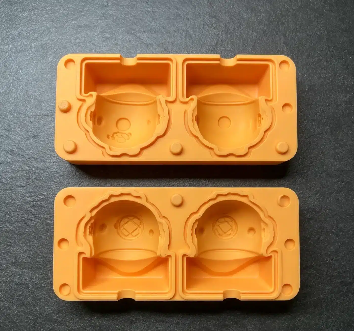
Core shift is the steel moving. The rubber then freezes the mistake as a wall that is 0.4 mm on one side and 1.6 mm on the other.
Deep hollow LSR parts (boots, bellows, liners, sheaths) hang a slender core in a hot cavity and inject a low-viscosity liquid. If the pressure field is higher on one side of a poorly supported core, the core walks. Elongation of the *part* will not push the core back. That is a parts cell.
On this site the analog is a mandrel in a poured RTV jacket. RTV pours around a mandrel mostly sag the jacket or let the core drift in a loose seat — not a jet from a cold-runner. The dump then copies a wedge wall. Support the mandrel in both halves, key the OD jackets, and do not treat 15A rubber as a centering spring.
HCR transfer can shift a mandrel too if the charge is off-center. Same locate-in-both-halves rule. Do not copy an LSR side-gate fix onto a compression biscuit or onto a pour box without looking at how the core is held.
What actually moves the core
A core is a cantilever or a floating pin. Forces on LIM:
- Unbalanced fill. One gate, or a family of gates that do not meet as a ring, loads one flank. The front races down the easy gap (already opened by the first millimetre of shift) and the thin wall gets thinner. Positive feedback.
- Jetting onto a face. A gate aimed at one OD will bend a long core before the cavity is full.
- Thermal growth. A core at 180 °C, a cavity plate at a different temperature, and a fit that was reamed at 20 °C. Loose is shift. Preloaded is wear and a seized pin.
- Injection rate. Fast fill on a long, thin core is a lateral slap. Slow fill on a hot thin wall is scorch.
- Vacuum and air circuits inside the core. A collapsing hose is not an I-beam.
On RTV the movers are quieter and just as real:
- Mandrel not seated in both jackets; a 0.3 mm low nest becomes a wedge.
- Jacket floppy (no mother mold) so the OD walks while the core stays — same wedge, opposite half.
- Pour from one flank that knocks a loose core.
- Thermal: a metal mandrel in a warm room versus a cold master. Less dramatic than 180 °C steel, still a fit.
If you ignore the first millimetre of walk, the defect is a “flow mark” that is actually a wedge-shaped wall and a leak test fail on the thin side — or a chocolate shell that breaks on the thin meridian.
Support the steel (or the mandrel) before you tune the process
DFM order:
- Two-sided support when the geometry allows: a core that seats in both halves, or a spigot into the moving half, beats a long cantilever. A small through-hole in the product that lets the core locate is cheaper than a hero cantilever. If the product cannot have a hole, say so and pay for the next items.
- Diameter versus length. A 4 mm core that is 60 mm long will walk. Increase root diameter, add ribs on the *core* in the non-cosmetic ID if the product allows, or split the core.
- Interlocks and taper seats that center as the mold closes. On RTV, keys on the OD plus mandrel seats in both jackets. Cold-fitted precision that binds at LIM temperature is how you break a core off in the part.
- Split or collapsible cores when the ID has grooves anyway. Shift and demold get solved together.
- Material of the core. Hardened stainless for LSR production hollows. On RTV, a CNC or printed mandrel that actually locates; aluminum is fine for a pour mandrel if the seats are real. Aluminum cores on a deep *production LIM* hollow are a tryout.
Stripper rings and air-eject still need a core that was *centered during fill*. Ejection cannot un-shift a cured wall. Peeling an RTV jacket cannot un-shift a dump that already copied the wedge.
Gating, pour path, and fill that do not bend the pin
LIM: ring gates, fan gates, or multiple drops that meet as a front around the core, not a single side gate on a 50 mm boot. Cold-runner balance that is mechanical. Heating one cavity to “slow it down” will not recenter a core. Vacuum so you are not fighting an air cushion on one flank.
RTV: pour path that wets around the mandrel as a ring, not a jet on one OD. Vacuum degas the mix; vacuum the box if the hollow is blind. Clamp/straps so the seats stay seated (see the clamp article). Flash on one OD is often the sister symptom of shift.
Wall thickness of the rubber is the other lever. A 0.5 mm wall on a long core has no stiffness to “hold” anything and every tenth of a millimetre of walk is a 20% thickness error. A 2 mm wall forgives more. If the product needs a thin, uniform sheath, you buy support and pour/gate discipline, not a hope that 20 Shore A will self-center.
Measurement: catch shift, not only OD
First article on a hollow should include wall map: ultrasonic, cut-up, or CT, at several depths and quadrants. OD within ISO 3302-1 and a crushed ID is a passed CMM on the wrong feature. Mark a clock on the part (or dump) relative to the gate or pour so you can see if the thin wall always sits opposite the fill.
Process capability on wall thickness is the core-shift study. If cavity 3 is always thin at 12 o’clock, that core or that drop (or that RTV seat) is the problem. Do not chase it with a global shrink factor. Platinum RTV shrink is already small (~0.1–0.3%); a wedge is not shrink.
RUUIPON Mold Structure Decision: Hollow? The third piece is usually a mandrel, not a third OD jacket. Two OD jackets plus a core is a 3-part mold. Large wet dump or soft Shore? → mother mold so the OD cannot sag off the seats.
Common mix-up: “silicone will center itself”
A lot of RFQs treat elongation as a locating feature. In the shop that usually means a cantilever mandrel and a wall map at T1.
What to ask when you're buying
- Process: LSR hollow *part* or RTV jacket + mandrel for a hollow *dump*?
- Core length and diameter; required wall and wall tolerance?
- Locating hole allowed? Gate/pour faces forbidden?
- Core-support concept in the design review, not after first dump?
- Wall map method (cut-up / UT / CT), clocked to the fill?
Worked example
You're casting a 120 mm lantern globe, 2.0 mm wall, two-part platinum RTV OD plus a CNC mandrel, 80 dumps. Seat the mandrel in both jackets, resin mother, pour as a ring, wall-map four quadrants at mid-height. A 4 mm × 60 mm cantilever with no far seat will walk. If the SKU is a 50 mm LSR boot at 40,000 / yr, that is a parts-OEM core-support and cold-runner balance review.
We would not recommend 20 Shore A as a centering spring
We would not recommend a single side gate (or a one-flank pour) on a long core, aluminum production LIM cores on a deep hollow, or a single OD and ID at the mouth as the only FAI. We would not chase a wedge with a shrink factor.
- Seat core in both halves -> Fill around the core?
- Fill around the core? - LIM -> Ring / balanced cold-runner
- Fill around the core? - RTV -> Ring pour + degas + jacket
- Ring / balanced cold-runner -> Wall map clocked to gate
- Ring pour + degas + jacket -> Wall map clocked to gate
- Deep hollow - Cantilever + hope -> Wedge wall
Typical shop values
Reference values only. Confirm material-specific limits against the supplier’s technical data and agree project acceptance criteria before production.
| Item | Typical shop value | | --- | --- | | RTV mix | Platinum 1:1 or 10:1; degas until the foam collapses | | Platinum shrink | About 0.1–0.3% — a wedge is not this | | LSR shrink (contrast) | About 2–3% | | Thin sheath warning | 0.5 mm wall: 0.1 mm walk is a 20% thickness error | | ISO 3302-1 | M2 common on OD; wall map is extra | | Jacket sag without mother | About 0.5–1.5 mm on a large tray — OD walk, same wedge |
Copy this into a hollow-core RFQ
- Process: LSR injection hollow or RTV OD jackets + mandrel
- Core length and diameter, required wall and tolerance
- Locating hole allowed; forbidden gate/pour faces
- Vacuum and air-eject assumptions
- Ask for the core-support concept before T1 / first dump
Send the hollow section and whether a through-hole is allowed. We'll seat the mandrel and key the OD, not hope the rubber centers. Custom RTV molds.
Related: 3-part splits, deep-draw demold, thin walls.
FAQ
Can a softer silicone grade reduce core shift because it “flows around” the pin? Softer grades often fill easier, which can lower the pressure you needed, but they do not recenter a bent core or a loose mandrel. Shift is the core moving under a pressure or seat difference. Fix support and fill balance. Using 20 Shore A as a centering spring is not a tool design.
Is core shift the same as shrinkage ovality? No. Shrink can oval a tube after it leaves a centered core; shift is a wedge wall that already existed in the mold. A cut-up that is thin toward the gate (or pour) on every shot is shift. Uniform thinness all around is more likely shrink, grade, or temperature.
Will slowing injection always stop a long core from walking? It can reduce the slap on LIM. It can also scorch a thin wall and still leave a thermal or support problem. On RTV, a slower pour helps only after the mandrel is seated. Use slower fill as a trial after support, not as the only lever.
Do HCR compression mandrels shift the same way? They can walk if the charge is off-center or the mandrel is loose in the plates, but the fill is a squeeze, not a jet from a cold deck. Locate the mandrel in both halves and place the biscuit so it does not hammer one flank. RTV is closer to this than to LIM jetting.
How many wall measurements prove a deep hollow is centered? Enough quadrants and depths to see a wedge. A single OD and a single ID at the mouth will miss a core that pivots. CT or a section at mid-depth plus the closed end is the usual honest map, clocked to the gate or pour.
Custom silicone development · DFM & prototype support
CAD, drawing, photos or sample details