
Retrofitting a Custom Gummy Tray to an Existing Depositor
If the depositor already exists, the tray should be treated like a replacement machine component, not a free-form silicone product.
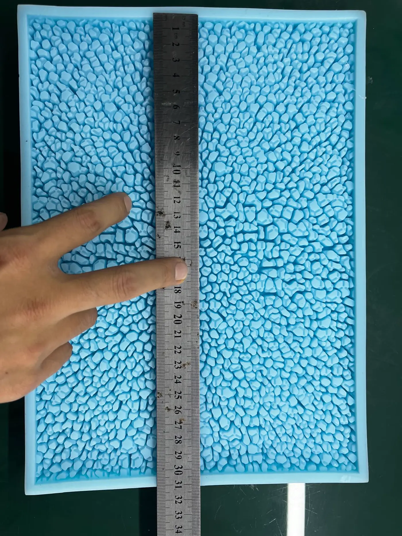
The first task is not cavity design. It is to capture the interface that the machine expects:
- tray outer dimensions;
- support/nest surfaces;
- nozzle count and pitch;
- first-nozzle datum;
- index distance;
- nozzle working height;
- clamp or conveyor clearances.
Only after those are fixed should cavity count, logo geometry and Shore be finalized.
Build a machine measurement sheet before CAD
A useful retrofit measurement sheet should contain four coordinate groups.
1. Tray envelope
Record:
- maximum length;
- maximum width;
- maximum total thickness;
- usable cavity area;
- leading/trailing-edge clearances.
2. Nozzle pattern
Record:
- number of active nozzles;
- nozzle center-to-center pitch;
- nozzle diameter;
- staggered pattern if any;
- whether nozzles are individually adjustable.
3. Datum system
Record:
- first nozzle to tray leading edge;
- first nozzle to tray side edge;
- locator-pin positions;
- tray stop position;
- index direction.
4. Z-height
Record:
- nozzle down position;
- tray top-plane height;
- cavity rim height;
- any nozzle insertion into the cavity.
A photo with a ruler is useful for initial review. It is not enough for a production retrofit unless the dimensions are actually verified.
Decide whether the silicone or the rigid nest carries the datum
Flexible silicone is good at release. It is not the ideal machine datum.
If the existing depositor uses a rigid tray nest, let the rigid component control:
- X/Y location;
- top-plane height;
- edge stops;
- clamping.
Then let the silicone tray control:
- cavity geometry;
- release;
- logo/texture;
- food contact.
This separation reduces the chance that a soft tray stretches into a different machine position after repeated handling.
Match cavity rows to the actual deposition sequence
Do not assume one nozzle = one cavity.
A 10-nozzle head can be used with:
- 10 cavities per shot;
- 20 cavities in two index positions;
- 30 cavities in three index positions;
- fewer cavities if selected nozzles are disabled.
The tray layout should be based on the production recipe.
For an indexed machine, verify:
row pitch = actual machine index distance
A small mismatch compounds across the tray. The first row can look correct while the last row misses the nozzle center.
First-cavity datum is the critical retrofit dimension
Pitch only controls spacing between cavities.
It does not tell the machine where the whole grid begins.
A retrofit drawing should explicitly state:
- leading edge → first cavity center;
- side datum → first cavity center.
If this is omitted, the entire grid can be offset while every local cavity pitch remains correct.
Prototype one full-size tray, not a miniature coupon
A small sample can validate:
- silicone release;
- logo detail;
- cavity surface.
It cannot validate:
- machine fit;
- nozzle alignment;
- loaded tray flatness;
- index error;
- edge clearances.
For a retrofit project, the first prototype should usually have the real tray envelope.
Dry-fit the machine before depositing food
Before hot pectin or gelatin is introduced:
- install the prototype tray;
- verify all locating surfaces;
- lower nozzles slowly;
- check nozzle-to-cavity centering;
- index every row;
- check Z-height;
- verify the tray does not slide;
- inspect edge/clamp clearance.
This turns an expensive food trial into a simple mechanical validation.
Water or gel tests have limited but useful value
A water or non-production gel test can help reveal:
- gross shot alignment;
- cavity overfill;
- splash paths;
- obvious tray tilt.
But it does not prove:
- pectin viscosity behavior;
- logo fill;
- real demolding;
- finished weight after drying;
- food-line production stability.
Use it as an intermediate check, not final approval.
Run a center/edge/corner fill-weight study
After the mechanical fit passes, use the real formula.
Record finished piece weight from:
- center cavities;
- long edges;
- short edges;
- corners.
If a position trend appears, investigate:
- tray sag;
- nozzle flow imbalance;
- machine leveling;
- support-nest contact;
- deposit temperature;
- index accuracy.
Do not immediately edit cavity volume.
Define the approval gate before multiplying 50-100 trays
A useful production-release checklist can require:
- dry-fit pass;
- nozzle center alignment pass;
- full-row indexing pass;
- loaded flatness within agreed process requirement;
- finished average weight within target band;
- center/edge/corner weight pattern acceptable;
- clean demolding;
- logo/detail accepted;
- food-contact document package confirmed.
Only after these are closed should the tray be multiplied.
Existing RUUIPON content relationship
P46 covers how to design depositor-compatible geometry from machine dimensions.
P51 is different:
how to retrofit, validate and approve one tray against an existing machine before multiplying production quantity.
Keep both pages, but avoid repeating the same nozzle-pitch explanation in full.