
Thin-Wall 0.2 mm: RTV Flash vs Designed Walls
0.2 mm is a local LSR fill limit, not an RTV cavity spec. On a poured mold, 0.2 mm is usually flash or a detail coat — not a part-wide wall you dump into.
 Kyler Yang · Founder8 min read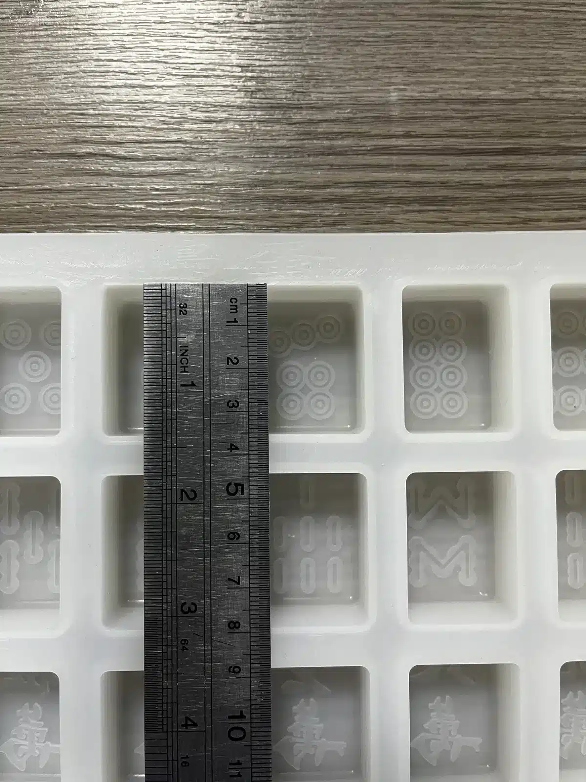
0.2 mm is an edge, not a default wall. Some LSR grades will fill a short membrane at that thickness in a hot, vacuumed, well-gated steel tool. Many will not. A postcard-sized 0.2 mm panel from a single gate is a different request from a 0.2 mm web next to a 1 mm feeder.
On this site you are usually buying a poured RTV cavity, not a thin LSR part. 0.2 mm on an RTV drawing is almost always one of three things: flash at a split you did not key, a detail-coat skin you brushed on the master, or a designed *cast* wall that needs a core, vacuum, and a cooperative mix. Treat 0.2 mm as a capability trial on the real span, not as a catalog promise for a chocolate tray.
HCR compression does not live here. Millable rubber is the wrong viscosity. Platinum RTV will copy a 0.2 mm flash faithfully and will struggle to *cast* a 0.2 mm designed wall unless you have a core and a degassed pour.
Fill is a race — different clocks
LSR is a liquid that shear-thins, then it starts to crosslink in the hot cavity. A thin section has little thermal mass. It heats through quickly. That is good for cycle time and bad if the front skins before the last millimetre fills. Flow length / thickness, grade viscosity, cavity temperature, injection rate, and vacuum decide whether a 5 mm run at 0.2 mm fills. A 40 mm run usually does not.
RTV is not in a race against scorch at 180 °C. The race is air and gel. Mixed platinum sits in a cup with a pot life. Vacuum degas until the foam collapses (about −0.095 MPa). A 0.2 mm designed gap around a core will trap air unless you vent the last-fill corner or pull vacuum on the box. A detail coat (brush or spray a thin platinum film on the master, gel, then pour the bulk) is how you copy micro-lettering without a 0.2 mm *structural* wall.
If you ignore last-fill air, the defect is a lacy edge that looks like the grade “cannot do 0.2 mm” when the grade never saw a clear path.
Cure, tear, and the wall that survives demold
A 0.2 mm LSR wall can cure in a few seconds and then tear on a pin or a thumbnail. Draft, polish versus texture, and ejection method are part of the thickness spec. Mirror cavities vacuum-lock thin membranes. Heavy texture on a 0.2 mm wall is a perforation pattern.
On an RTV mold, the working wall is typically 8–15 mm of 10A–20A rubber behind a jacket — not 0.2 mm. If you specify a 0.2 mm RTV skin as the whole tool, you have a glove that tears on the first peel. Detail coats are extra; they are not the jacket.
Use is the third limit. A 0.2 mm diaphragm that fills and ejects may still crease or fail a burst test. Tear strength (ASTM D624) and elongation (ASTM D412) belong in the grade pick. A pretty 0.2 mm web in a 10 Shore A gel is not a 0.2 mm valve in 50 Shore A — and it is not a dump cavity.
ISO 3302-1 will not save a membrane. Thickness tolerance on a 0.2 mm wall is a large *percentage* even when the millimetre number looks fine. Contact probes dent 0.2 mm rubber. Optical methods with a written edge rule.
Tooling that makes 0.2 mm less of a stunt
For LSR parts (other factory): steel, uniform cavity heat, vacuum, flash control (the same low viscosity that fills 0.2 mm will leak ~0.005 mm at the land), valve gates, mechanical runner balance. Do not specify 0.2 mm on a whole housing to “save material.”
For RTV molds (this site):
- Core the thin *cast* feature; do not ask a solid pour to form a 0.2 mm membrane unaided.
- Detail-coat the master for micro-graphics; then pour a real wall.
- Keep 0.2 mm away from the split. Flash at a keyed joint will look like a designed thin wall and then tear.
- Vacuum the box on blind pockets.
- Measure the *dump*, not a probe parked on a floppy 0.2 mm RTV lip.
FDA 21 CFR 177.2600 and ISO 10993 do not create thin walls. They constrain which grades you may even try.
RUUIPON Mold Structure Decision: Flat back? → open-back. Thin designed cast wall with a core? → two-part / plug / inner core. Soft Shore 10A–20A or wet dump? → mother mold. Do not use a 0.2 mm glove as the structure.
Common mix-up: 0.2 mm flash as a “thin-wall mold”
A lot of RFQs treat a flashed split as evidence the shop can mold 0.2 mm. In the shop that usually means the keys did not seat. Flash is not a capability plaque.
What to ask when you're buying
- Is 0.2 mm a local *part* membrane (LSR OEM) or a feature on the *cast* article from an RTV cavity?
- Span, gate/pour side, and whether vacuum is assumed?
- Detail coat plus bulk pour, or a structural 0.2 mm skin?
- How will thickness be measured — optical, with an edge rule?
- Jacket wall (8–15 mm class) separate from the thin feature?
Worked example
You're dumping a 40 × 25 mm chocolate with a 0.3 mm logo web at the base, 12-cavity platinum RTV, about 3,000 dumps/season. Detail-coat the master, pour an 8–12 mm 15A skin, resin jacket. Do not CAD a 0.2 mm tray floor. If the product is instead a 0.2 mm LSR slit valve, that is a steel cold-runner trial on a parts OEM — different factory.
We would not recommend a 0.2 mm RTV tray floor to “save silicone”
We would not recommend HCR compression for a 0.2 mm production wall, a whole housing called out at 0.2 mm, or raising cavity heat (on LSR) as the only thin-wall lever. We would not treat a plaque fill as your flow length.
- Whose wall? - LSR part membrane, short span -> Steel, vacuum, feeder wall, trial
- Whose wall? - RTV mold / dump cavity -> Flash, detail, or structure?
- Flash, detail, or structure? - Split flash -> Keys + jacket — not a spec
- Flash, detail, or structure? - Micro-graphics -> Detail coat, then bulk pour
- Flash, detail, or structure? - Designed cast membrane -> Core + vacuum + real RTV wall
Typical shop values
Reference values only. Confirm material-specific limits against the supplier’s technical data and agree project acceptance criteria before production.
| Item | Typical shop value | | --- | --- | | LSR local membrane | 0.2 mm is a short-flow trial; many production walls sit at 0.5 mm and up | | LSR leak / flash band | About 0.005 mm at the land | | RTV working wall | Often 8–15 mm, Shore 10A–20A with a rigid jacket | | Platinum mix | 1:1 or 10:1; degas until the foam collapses | | Platinum shrink | About 0.1–0.3% | | ISO 3302-1 | M2 common; local optical tolerance on a 0.2 mm feature |
Copy this into a thin-wall RFQ
- Object: LSR injection part or RTV cavity for a dump/cast
- Thin feature: thickness, span, which side is gated or poured
- Vacuum yes/no; detail coat yes/no
- Measurement method (optical + edge rule)
- Jacket wall and Shore if this is a mold
Send the STEP with the thin feature circled and whether this is a part or a cavity. We'll say if it is a detail coat, a core, or a parts-OEM trial. Custom RTV molds.
Related: draft vs texture, core shift in hollows, food-grade molds.
FAQ
Is 0.2 mm a guaranteed minimum wall for all LSR parts? No. It is a local limit that depends on grade rheology, flow length, cavity heat, vacuum, and gating. Short webs next to a feeder can make it; large panels usually cannot. Quote 0.2 mm as a trial on the real span, not as a catalog wall.
Why did a 0.2 mm plaque fill but the part shorted? The plaque was not your flow length, gate, or last-fill trap. Air in a dead-end membrane looks like a short. Copy the part’s path in the study, including vacuum, or the plaque is a souvenir. Same lesson on RTV: a cup coupon is not a 0.2 mm core gap.
Can HCR compression mold a 0.2 mm wall? Not as a production default. Millable silicone does not flow like LSR. If the product must be 0.2 mm, you are in LSR injection territory, or you are redesigning. RTV will copy flash at that thickness; that is not a designed wall.
Will a 0.2 mm membrane hold ISO 3302-1 tolerances? Thickness tolerance on a 0.2 mm wall is a large percentage even when the millimetre number looks fine. Agree optical measurement and a local tolerance. Do not expect a blanket class to make the membrane magic.
Does a 0.2 mm RTV mold wall work if LSR can fill 0.2 mm? No. LSR fill of a *part* is not RTV *tool* wall. A poured mold needs a real skin and usually a jacket. Use 0.2 mm for a local cast feature or a detail coat, not as the tray.
Custom silicone development · DFM & prototype support
CAD, drawing, photos or sample details