
Designing Silicone Gummy Trays for Commercial Depositors
A commercial gummy tray should be designed as a machine interface.
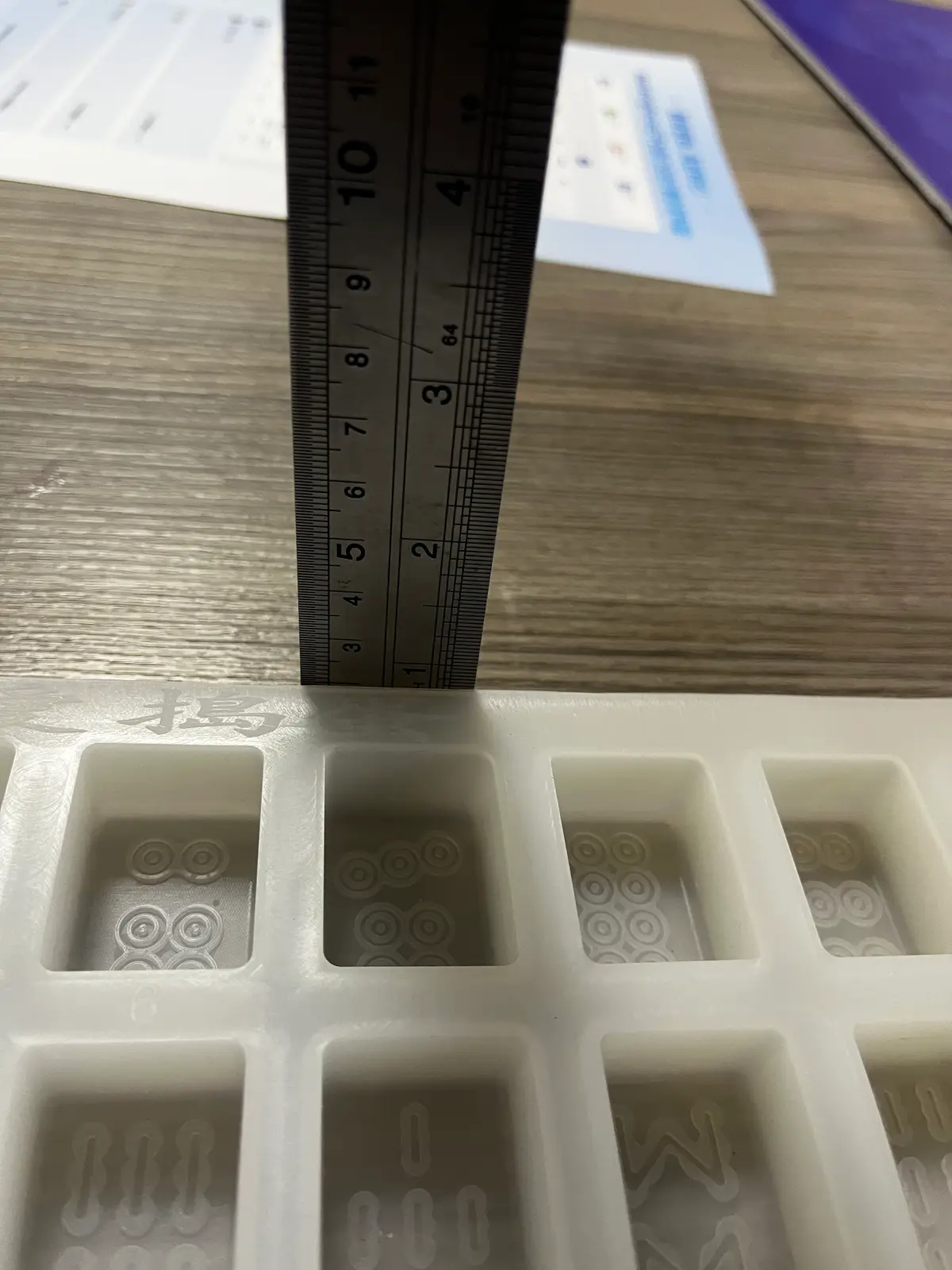
The controlling dimensions are not only cavity diameter and depth. They include:
- nozzle pattern;
- nozzle pitch;
- first-nozzle datum;
- row/index spacing;
- tray outer dimensions;
- nest/locator geometry;
- nozzle Z-height;
- scraper or conveyor clearance.
If those dimensions are not locked, "compatible with a depositor" is not an engineering statement.
Start with the machine envelope
Before laying out cavities, record:
- maximum tray length;
- maximum tray width;
- maximum allowable tray height;
- conveyor or shuttle width;
- locator-pin/nest features;
- clamping surfaces;
- required leading-edge orientation;
- any keep-out areas.
The silicone tray may sit inside a rigid support/nest. In that case, the machine interface can belong to the rigid carrier rather than the flexible rubber.
This is usually more repeatable than locating a soft tray directly.
Nozzle count does not automatically equal cavity count per row
Suppose the depositor has 12 nozzles.
Possible tray strategies include:
- 12 cavities deposited simultaneously;
- 6 cavities with every second nozzle disabled;
- 24 cavities filled in two indexed positions;
- multiple lanes depending on machine stroke.
The correct tray depends on the actual line sequence.
Ask for the machine recipe or motion description, not just the nozzle count.
Nozzle pitch is center-to-center geometry
The cavity centerline should be coordinated with the nozzle centerline.
The RFQ should state:
- nozzle pitch X;
- row pitch Y;
- whether pitch is fixed or adjustable;
- usable nozzle diameter;
- any nozzle staggering.
A beautiful symmetric cavity grid is useless if it misses the machine pattern.
First-cavity datum is where many custom trays fail
Pitch alone is not enough.
You also need a starting reference.
Example:
- tray leading edge → first cavity center = X;
- tray side datum → first cavity center = Y.
Without that relationship, every cavity can have the correct pitch and the entire grid can still be offset from the nozzles.
This is why the depositor drawing should include a datum scheme.
Z-height affects cavity opening and splashing
Nozzle vertical position influences:
- stringing;
- splash;
- air entrapment;
- whether the nozzle enters the cavity opening;
- clearance over logo/texture features;
- contact risk with flexible silicone.
Check:
- lowest nozzle position;
- tray top-plane height;
- expected loaded/supported tray height;
- cavity rim/opening geometry.
If the silicone tray sags, nozzle Z relationship can vary across the sheet.
That becomes a support/flatness problem as well as a depositing problem.
Indexing and row spacing must be proven in motion
If the machine fills multiple rows by indexing:
- confirm travel per index;
- confirm which edge is the machine reference;
- include acceleration/stop behavior if the tray can slide;
- ensure the support nest prevents rubber movement;
- verify the last row does not hit a clamp/fixture.
A static CAD screenshot can miss these operational constraints.
Flood-and-scrape is a different interface
Flood-and-scrape may not use one nozzle per cavity.
The controlling features become:
- top-plane flatness;
- scraper clearance;
- cavity rim consistency;
- overflow management;
- tray support under scraper force;
- clean outer border.
Do not copy nozzle-pitch logic into a flood-and-scrape tray.
P48 should handle that process separately.
Dry-run the machine fit before food testing
Before depositing hot gummy mass:
- install the prototype tray and support;
- confirm all locators engage;
- jog the machine slowly;
- bring nozzles to working Z;
- verify cavity center alignment;
- index every row;
- inspect clearances;
- record any offset;
- revise CAD if necessary.
This separates mechanical-fit errors from formula/process errors.
Then test with actual gummy mass
After machine fit passes, validate:
- shot alignment;
- fill completeness;
- splashing/stringing;
- piece weight;
- center/edge/corner variation;
- demolding;
- loaded tray flatness;
- cleanup around the cavity rim.
Machine fit is necessary but not sufficient.
What not to claim on RUUIPON
Existing broad gummy content currently makes unsupported "compatible with all major depositor brands" style claims.
That should be removed unless RUUIPON has first-hand validated drawings/test records for the named equipment.
A stronger statement is:
We design the tray around the depositor dimensions you provide and validate the prototype against that interface.
That is more credible and technically correct.
What to ask the customer for
Send this worksheet:
- Depositor brand/model:
- Drawing/manual page:
- Nozzle count:
- Nozzle diameter:
- Nozzle pitch X:
- Row/index pitch Y:
- First-nozzle datum from tray edge:
- Maximum tray OD:
- Tray locator/nest drawing:
- Nozzle working Z range:
- Fill method:
- Target grams:
- Formula family:
- Scraper clearance if applicable:
- Desired cavities per tray:
The mold quote is custom silicone gummy molds. Finished grams versus cavity millilitres are on cavity volume vs target weight.